Linear Audio High-voltage Delay for Tube Amplifiers V4
This high voltage delay for tube amplifiers was designed by Jan Didden of Linear Audio and published in the October 2019 issue of audioXpress.
Why you need it
Tube heaters need some time to heat up, before a tube starts conducting. Depending on the tube type this can range anything from a dozen seconds to a minute. In itself this is no problem – you just wait a little bit before your music starts playing.
But normally the high-voltage supply for that tube comes on at the same time as the heater voltage comes on, often supplied from the same transformer. That means that the tube sits there for up to a minute with high-voltage applied and no conduction. This may shorten tube life; it depends on the tube type and the actual high voltage, and the jury is still out on how significant it is, but the effect is known.
Another issue is that the high voltage initially, when the tubes do not yet draw current, can be quite a bit higher than the voltage under load, putting additional stress on the tubes and possibly the high-voltage capacitors. up, before a tube starts conducting. Depending on the tube type this can range anything from a dozen seconds to a minute. In itself this is no problem – you just wait a little bit before your music starts playing.
But normally the high-voltage supply for that tube comes on at the same time as the heater voltage comes on, often supplied from the same transformer. That means that the tube sits there for up to a minute with high-voltage applied and no conduction. This may shorten tube life; it depends on the tube type and the actual high voltage, and the jury is still out on how significant it is, but the effect is known. Another issue is that the high voltage initially, when the tubes do not yet draw current, can be quite a bit higher than the voltage under load, putting additional stress on the tubes and possibly the high-voltage capacitors.
So we should not take chances with limiting the life of our precious tubes, and switch on the high voltage only after the cathodes have been properly heated up. I set about to design this unit, making it self-sufficient so no separate supply is needed. For flexibility, the delay can be simply set to anything between 20 seconds and 254 seconds, which should cover all requirements.
The circuit
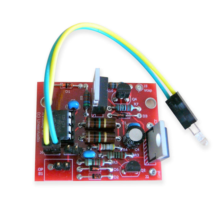
The small pcb is easy to integrate even in existing tube amps, and it switches on the high voltage on a zero mains crossing to avoid loud thumps in the speaker. And, of course, no impact on amplifier audio performance!
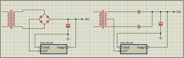
The topology is shown in figure 1. By inserting the switch in the return line to the power transformer I leave everything after the last reservoir cap unchanged. So there is no impact on the power supply quality and no messing up any carefully laid out ground circuitry. It can be used either with a bridge-type rectifier or a center-tapped secondary with a double-phase rectifier as shown.
With a Center Tap transformer, the board is connected between Gnd and Center Tap. With a full bridge rectifier, it is connected between ground and the gnd output of the diode bridge. Easy, simple, no risk.
The unit is powered by a very small current stolen from the high voltage, the Vcap connection.
A small controller chip is used for all the precise timing actions. This chip is only active at switch-on, and when the supply is switched on, it turns itself off and goes to sleep. The kit includes the controller chip that fits in a standard DIL08 socket.
Delay time
The controller is set for a delay of 30 seconds out of the box. You can set it to your needs as follows. After installing the board and verifying it works, switch the amp off. Determine the delay you'd want to set, and divide that number by two. Place jumper JP1, and switch on the amp. The LED will start flashing in a 2 second rhythm, so you count off the number you have previously determined. When you get to zero, pull off the jumper. That's all – you have now set the delay to the time you want!
Important note: be careful when handling a jumper with the amp on, since high voltage is present on the board. You are responsible for your safety, not me, not the publisher. If you anticipate experimenting, you could replace the jumper with one of those small PCB toggle switches, they should fit the 0.1in pitch, but use a switch with a plastic or isolated lever. Jumpers are available with a little extra 'handling strip' so you can remove them without touching the jumper itself. Better yet, use a pliers with insulated handles.
The LED that flashes during the delay stays on or goes out after the delay has passed. This is set by jumper J5. If J5 is present, the LED goes out after the delay. This saves a few high-voltage milliamps and is preferred if you already have a pilot light on your amp front panel.
THE SPECS
There's only a few: absolute max voltage (that is the max at your supply cap, when switching on the amp, before it is warmed up!): 500V*. This is where the big guys would say: 'exceeding this maximum spec may permanently damage the device'... Max high voltage supply current that can be switched has no practical limit; if you have an amp that takes more than a couple of amps, you probably operate a transmitter and even then, no sweat! The delay time default is 30 seconds and can be changed to any value, in 2 sec steps, between 20 and 254 seconds.
*There is an option to extend the max voltage to 600V, by replacing the supplied IXTP1R6N50D2 with an IXTP01N100D, but these are not readily available.
Construction and article download
Full schematics, board layout, parts list and construction tips are in the audioXpress article. Our friends at AX have courteously agreed to make the article available for free download for diyaudio members.
Note that the kit as provided has an absolute max input voltage of 500V. There is an option to extend the absolute max input voltage to 600V, by replacing the supplied IXTP1R6N50D2 with an IXTP01N100D, but these are not readily available.
The diyAudio kit contains the PCB, the controller, the two power FETs and the low current LED. Everything else is common stuff you may already have or can easily get.
Get the article, get the kit, make your tube amp so much more reliable and prolong tube life. What's not to like?