
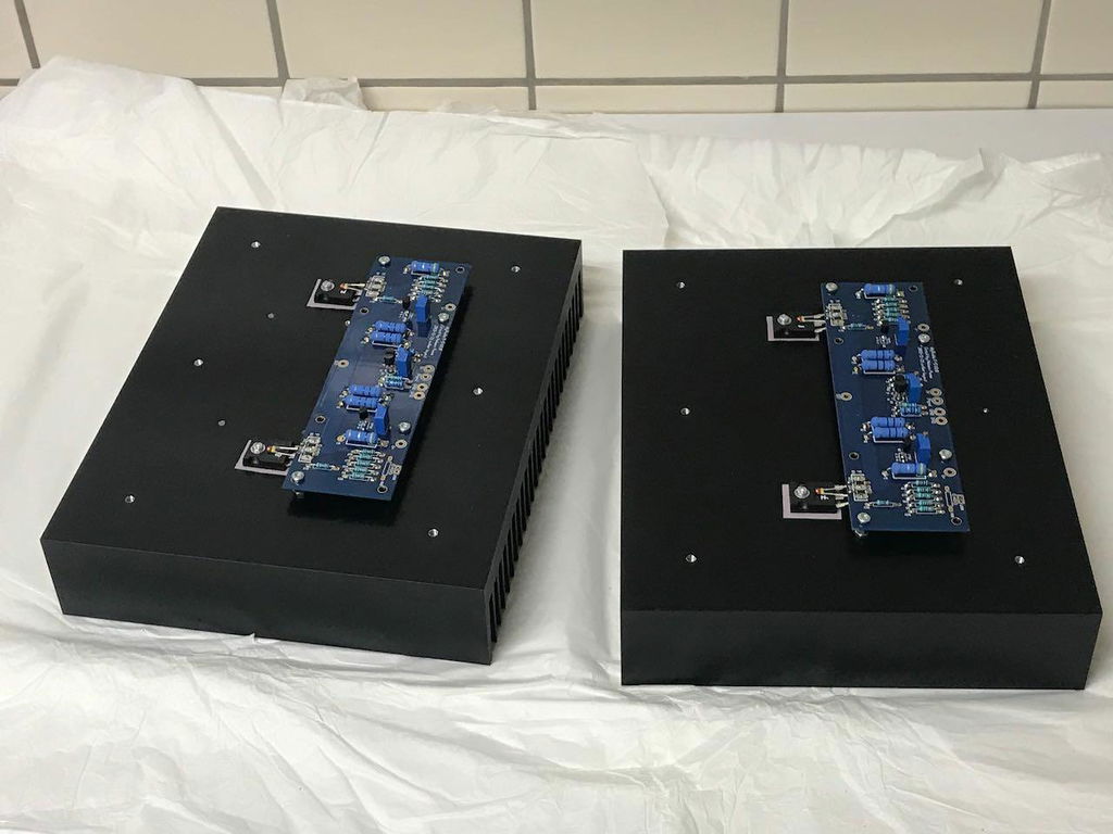
F5
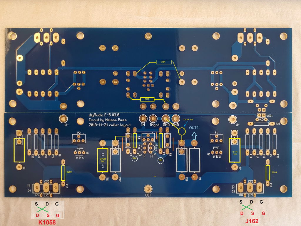
- 2 x F5 Amplifier PCBs
| Dimensions | 170mm x 50mm |
|---|---|
| Mounting holes | UMS Heatsink Compatible |
| Board Revision | 3.0 |
The F5 is one of the earlier First Watt designs featured on diyAudio. At one time, the F5 was probably the most popular amplifier being built by diyAudio enthusiasts; a timeless design from Nelson Pass.
The F5 is a Push-Pull, Class-A power amplifier. It is unique in that it has no capacitors in the amplifier circuit. The F5 is a voltage source amplifier, requiring nothing out of the ordinary from your preamp or speakers. It is simple to build, sounds fantastic, and has similar gain to many commercial amps.
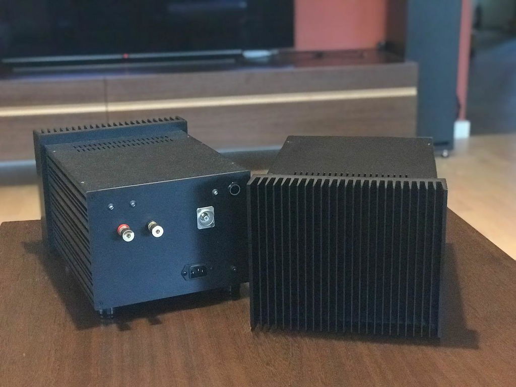
Populate these boards with your components, then add your own power supply, chassis and heat sinks to complete the amplifier.
Power supply requirements
A bipolar power supply of (+/- 24V) is required. The PSUs for almost all First Watt amplifiers including the F4, F5, F6, M2x, Aleph J, and Aleph Jzm are identical. The same PSU can be used for all of them.
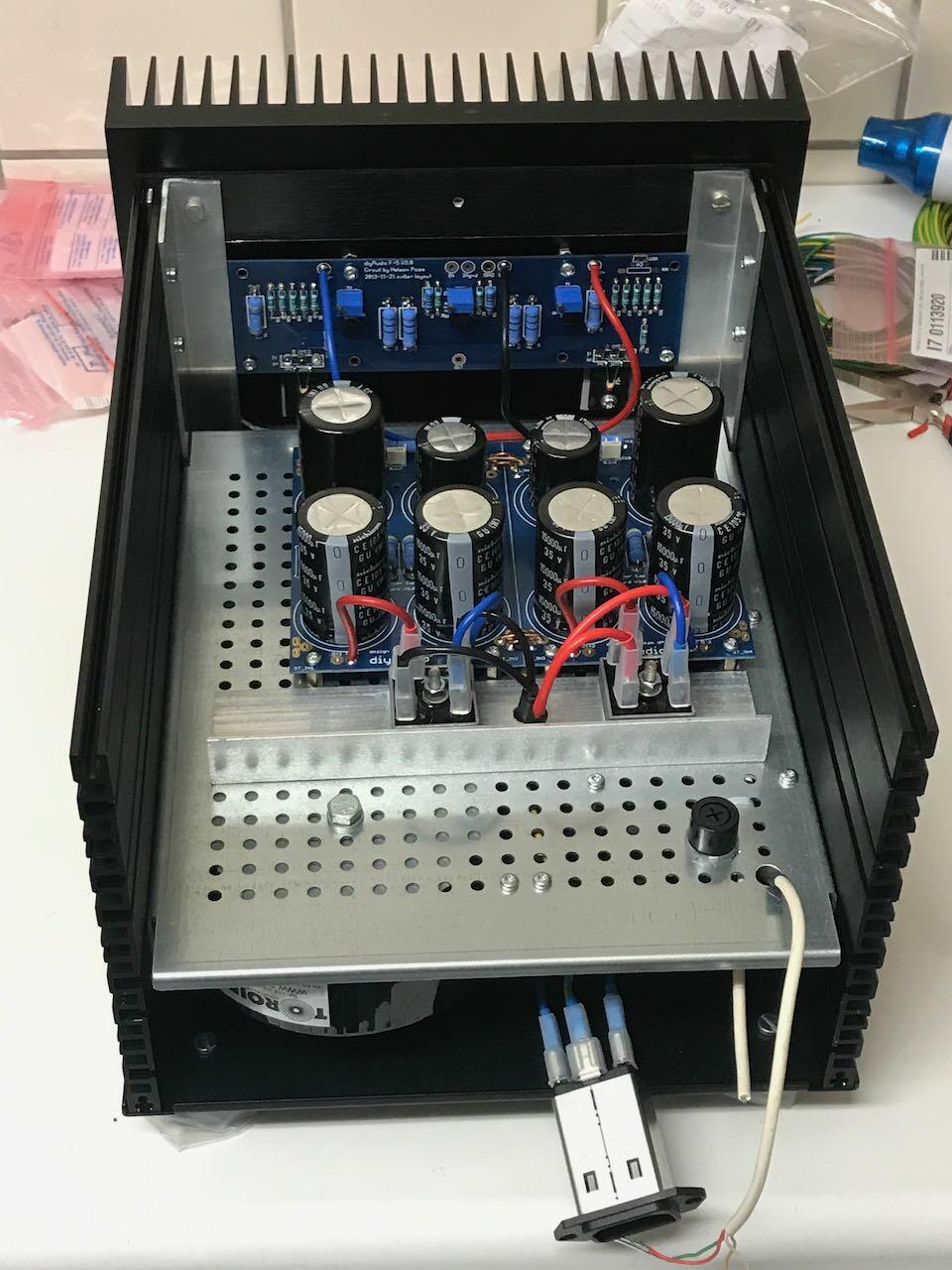
The Simple Linear Bipolar Power Supply is the choice for DIYers that prefer a higher performance power supply, but enjoy the convenience of a full kit. For builders that prefer to choose their own parts, the PCBs are also available.
- The Universal Power Supply PCBs allow the experienced DIYer to choose every part of their PSU or use what they have in their spare parts bin.
Chassis suggestions
The 3U Deluxe is an excellent choice. For builders that want more space and/or may want to build a bigger amplifier in the future, the 4U Deluxe or 5U Deluxe are great choices. We also have a back panel parts kit to make life easier, and don’t forget the Keratherm.
Key Information
- Power Amplifier Project
- Designed by Nelson Pass
- Intermediate Difficulty
- Only Essentials Kit Available
- Comprehensive Build Guide
Highlights
- The Classic First Watt F5
- Advanced DIYers can "tune" their distortion profile to taste
Links, Discussion & Files
- diyAudio F5v3 Build Guide
- V3 Schematic (Included in the F-5 Turbo Article) (PDF)
- V3 Schematic itself extracted from the F-5 Turbo Article (JPG)
- diyAudio Store F-5 Helpdesk Thread
I am very happy withe the result.
I replaced an ancient NAD 2150 with this and am very happy with the result. My system consists of a DIYINHK DAC driving the amp, and a pair of Linn Keilidh speakers.
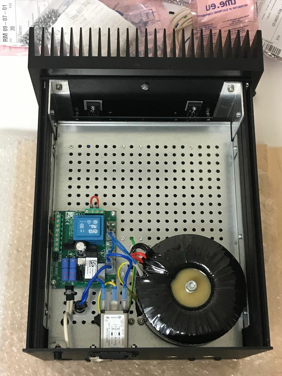
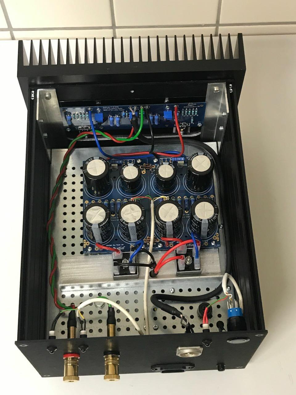
The circuit boards are high quality and the assembly is straight forward. I went with the deluxe chassis, universal power supply, and the soft start/speaker protection boards. The build guide and help thread were very helpful.
I can find no flaws with the sound quality. It is very clean and clear. Voices in particular stand out. Bass has plenty of punch. Complex musical passages with lots going on remain clear. It has plenty of power to drive my speakers to above reasonable listening levels.
My compliments to Nelson Pass for the circuit design, and to the DIY Audio Store crew for making it possible.
Very good board.
I modified the F5 board to F7.
1-Cut 3 places (orange line).
2-Add 2 resistors back face.
3-Cross drain pin & sorce pin of power mos-fets.
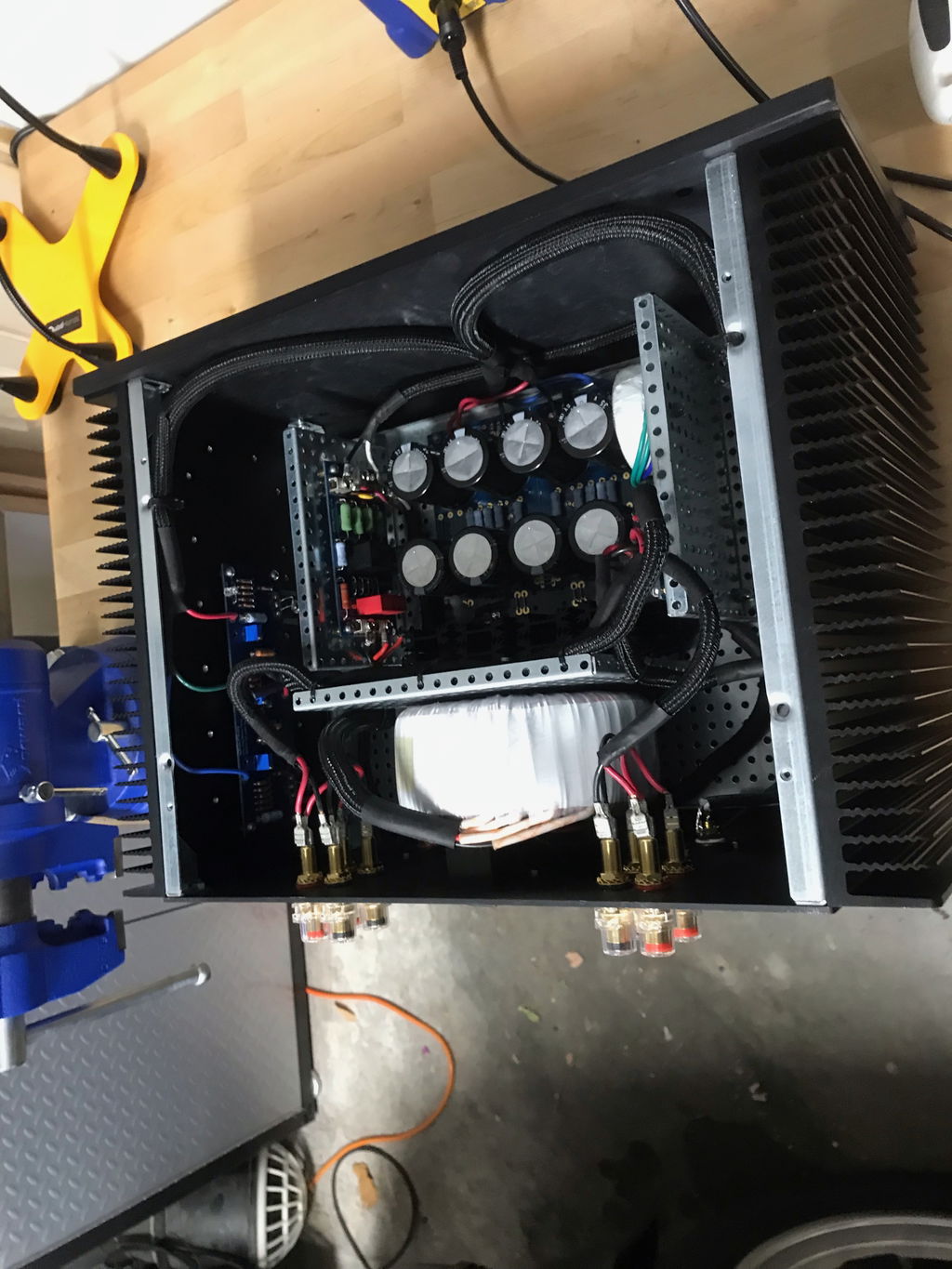
So last night I finished my F5 amplifier.
It uses these boards and is a text book build; everything went to plan, and it sounds great.
A 300 watt Toroidy Audio Grade transformer is being used, which seems fine.
Two tips:
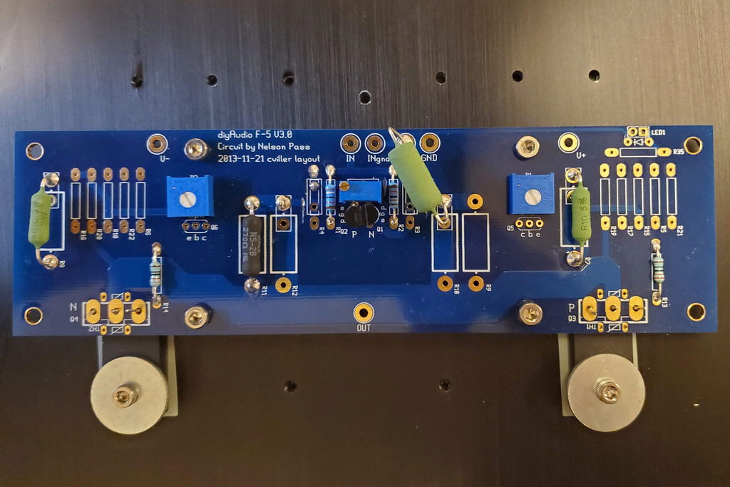
1 - when soldering R7 & R8 think about how you will attach your multi meter during the bias setting stage. I have them standing off the board a little, and my test hooks clipped on easily and safely.
2 - when setting P1 and P2 to zero, triple check that the resulting resistance across R5 & R6 is low not high. This could require clockwise OR anti clockwise adjustment depending on how you position P1 & P2 on the board. When setting bias for the first time, expect no change for a few turns, then a rather sudden increase in voltage.
Top quality boards. Top service and fast shipping. Build zhe F5 and Im truly happy with the sound. Thanks Diyaudio store!
Absolutely love these boards! Very nice quality board, and the layout is superb. DIY Audio never disappoints!